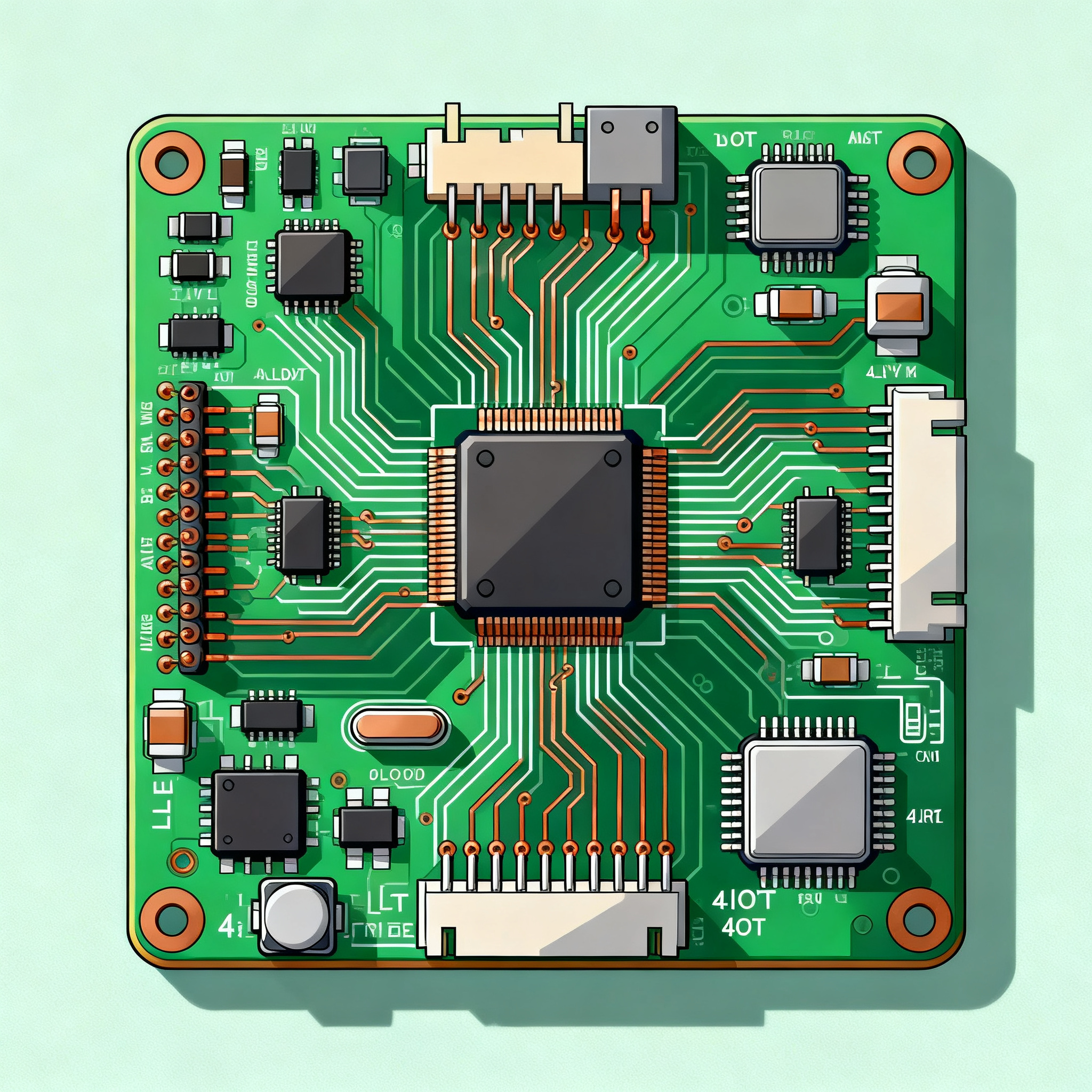
5 Cost Optimization Tips for 4-Layer IoT PCB Manufacturing & Assembly
5 Cost Optimization Tips for 4-Layer IoT PCB Manufacturing & Assembly Why IoT PCB Costs Spiral Out of Control — And Where to Start Cutting IoT hardware teams often watch their 4‑layer PCB budgets ball...
5 Cost Optimization Tips for 4-Layer IoT PCB Manufacturing & Assembly
Why IoT PCB Costs Spiral Out of Control — And Where to Start Cutting
IoT hardware teams often watch their 4‑layer PCB budgets balloon right when they’re ready to scale. The culprits aren’t always obvious. A design that worked perfectly on the bench can hide tolerance penalties, component lead‑time surprises, and testing overkill that quietly add 20–30% to the final invoice. Understanding where the money leaks is the first step to plugging the holes.
One of the most expensive habits is specifying unnecessarily tight trace widths and spacing. According to a detailed cost‑optimization guide from AllPCB, relaxing trace/space from 4 mil to 6 mil can reduce fabrication defects and lower costs by 10–15% [1]. That’s a direct hit to your bottom line, and most IoT microcontrollers and sensor interfaces function perfectly at 6 mil.
Supply chain shocks are another budget killer. Non‑standard components or exotic materials can trigger lead‑time surprises that force expensive spot buys or line‑down situations. The same AllPCB analysis emphasizes that using widely available components and maintaining open communication with your manufacturing partner is the best defense against bottlenecks [2]. When a single out‑of‑stock connector delays a 500‑unit run, the cost of air freight and re‑scheduling dwarfs any unit‑price savings.
To see the full picture, you need to break down the total cost stack. RapidDirect’s assembly cost guide lays out the equation clearly: Total Cost = PCB Fabrication + BOM + Assembly Labor + Value‑Added Services (Programming/Coating) + Testing (AOI/X‑Ray/FCT) + Logistics/Tariffs/Exchange Rates [3]. A standard 500‑unit run of a 4‑layer IoT sensor board makes every one of those line items visible, and small changes in any category ripple through the total.
Finally, don’t overlook the cost of defects. A NovaPCBA article on 4‑layer assembly cost optimization points out that collaborating with your manufacturer and following design rules minimizes defects that would otherwise require rework or scrap [4]. Every lifted pad or solder bridge on a tight‑pitch IoT board erodes the margin you fought to protect. The five tips that follow address these pain points head‑on, giving you a practical roadmap to cut costs without compromising the reliability your connected product demands.
The Anatomy of a 4‑Layer IoT Board: What Drives Fabrication and Assembly Costs
Before you can optimize, you need to know exactly where your money goes. A 4‑layer IoT PCB — think a compact sensor node with a wireless MCU, a few sensors, and a power management section — has a cost structure that’s surprisingly consistent across volumes. Using the 500‑unit example from RapidDirect’s guide [3], we can map the typical distribution. The table below breaks down the major cost drivers and shows which levers you can pull.
| Cost Component | Typical % of Total | Key Drivers | Optimization Levers |
|---|---|---|---|
| PCB Fabrication | 20–30% | Layer count, material (FR‑4 grade), surface finish, trace/space, via size, panel utilization | Relax tolerances, consider 2‑layer if possible, use standard FR‑4 and HASL (if fine‑pitch allows) |
| Bill of Materials (BOM) | 35–50% | Component selection, package sizes, availability, MOQ pricing | Choose standard, multi‑sourced parts; avoid EOL or niche packages; leverage volume discounts |
| Assembly Labor | 10–15% | Number of SMT placements, through‑hole parts, manual soldering, programming time | Minimize unique part numbers, consolidate to one side, use automated programming where possible |
| Value‑Added Services | 5–10% | Conformal coating, potting, firmware loading, functional testing setup | Only apply coating where environmental exposure demands it; batch‑program before assembly |
| Testing & Inspection | 5–10% | AOI, ICT, flying probe, X‑ray, functional test development | Use AOI as baseline; reserve ICT/X‑ray for BGAs or critical nets; rely on functional test for low‑complexity boards |
| Logistics, Tariffs & Overhead | 5–10% | Shipping method, origin/destination, duties, inventory carrying cost | Plan standard lead times, consolidate shipments, consider regional manufacturing |
Fabrication and BOM together eat up 55–80% of the total, so they deserve the most attention. The layer count alone is a powerful lever: switching from a 4‑layer to a 2‑layer board can save up to 30% on material and processing costs [1]. However, for many IoT designs with mixed‑signal requirements, a solid ground plane on layer 2 and power on layer 3 is non‑negotiable. The trick is to avoid “layer creep” — adding planes just because you can — and to challenge every inner layer’s necessity.
Testing is another area where IoT teams often overspend. A 4‑layer board with a QFN wireless module and a few sensors rarely needs full ICT or X‑ray. Automated optical inspection (AOI) catches 99% of solder defects, and a well‑designed functional test can verify the RF path and sensor readings. Reserve X‑ray for BGAs or hidden joints, and you’ll keep testing costs below 10% of the total.
Turnkey vs. Consigned vs. Hybrid: Choosing the Right Assembly Model for Your IoT Build
How you source components and manage assembly has an outsized impact on both cost and schedule. Three models dominate: turnkey (the assembler buys everything), consigned (you supply all components), and hybrid (you supply critical or proprietary parts, the assembler buys the rest). The right choice depends on your BOM complexity, volume, and in‑house procurement muscle.
Turnkey services consistently deliver savings of 10–15% by eliminating separate shipping, reducing lead times, and leveraging the assembler’s volume pricing [5]. For a 500‑unit run of a 4‑layer IoT board, turnkey assembly costs can land around $1,800, while consigned models often creep higher once you account for inbound freight, inventory management, and the risk of component shortages [5]. The table below compares the three approaches across the metrics that matter most to IoT product teams.
| Comparison Metric | Turnkey | Consigned | Hybrid | Selection Criteria & Failure Boundary |
|---|---|---|---|---|
| Cost per unit (500‑unit batch) | ~$3.60 (assembly only) or ~$18–25 total with BOM | Often 10–20% higher due to logistics and spot buys | 5–10% savings on proprietary parts, but overhead on managed BOM | Choose turnkey if BOM is standard; consigned only if you have better pricing on >50% of line items |
| Lead time | Shortest — assembler stocks common parts | Longest — you must kit and ship; delays from one part stall everything | Moderate — assembler procures standard parts while you supply the rest | If time‑to‑market is critical, turnkey eliminates kitting delays |
| Quality control | Assembler takes full responsibility; counterfeit risk is on them | You bear counterfeit and ESD risk; no single point of accountability | Shared risk; clear demarcation needed | For medical or safety‑critical IoT, turnkey with a certified partner reduces liability |
| Component sourcing risk | Assembler manages shortages; may substitute with approval | You absorb all allocation and EOL risks | Split risk; you handle proprietary parts, assembler handles commodity | If your BOM has long‑lead‑time sensors, consigned may be necessary — but buffer stock is essential |
| Best for | Standard IoT nodes, gateways, sensor boards with commercial‑grade components | Highly specialized designs with custom ASICs, pre‑programmed modules, or military‑grade parts | Designs with a few proprietary sensors or modules and the rest commodity | Start with turnkey; move to hybrid only when you have proven supply chain leverage |
Real‑world examples reinforce these trade‑offs. JHYPCB documented a case where a 4‑layer board was redesigned to 2 layers with optimized routing, saving $2 per board on a 500‑unit run [6]. While that saving came from the PCB fabrication side, it also simplified assembly and made turnkey even more attractive. On the planning front, RayPCB’s cost calculator guide emphasizes that planning orders to avoid rush charges and leveraging standard lead times is one of the highest‑impact strategies you can adopt [7]. Rush fees can add 25–50% to assembly costs, wiping out any BOM savings.
The balancing act between price, quality, and turnaround time is constant. As another industry comparison notes, you must avoid overpaying for unnecessary features while ensuring compliance with industry standards and meeting product launch deadlines [8]. For most IoT teams, a turnkey or hybrid model with a partner that offers free DFM feedback — like NovaPCBA’s standard service — delivers the best mix of cost control and reliability.
DFM Moves That Slash Costs Without Sacrificing Performance
Design for Manufacturability (DFM) isn’t a box to tick at the end of layout; it’s a continuous mindset that can cut 15–25% from your 4‑layer IoT board costs. The following five DFM moves are proven in volume production and require no exotic materials or processes.
1. Relax trace and space to 6 mil (or larger). As highlighted earlier, moving from 4 mil to 6 mil traces and spaces reduces fabrication defects and lowers costs by 10–15% [1]. Most IoT MCUs (e.g., ESP32, nRF52, STM32) and common sensors use 0.5 mm pitch or larger, which easily routes at 6 mil. Reserve 4 mil only for the few nets that truly need it, and you’ll keep the entire board in a cheaper process window.
2. Challenge every layer. The same AllPCB guide stresses that sticking to the fewest layers necessary can save up to 30% on material and processing costs [1]. Before committing to a 4‑layer stack, ask whether a 2‑layer board with a solid ground pour and careful routing can meet your EMI and signal integrity targets. If you must stay at four layers, use a standard stack‑up (e.g., SIG‑GND‑PWR‑SIG) that every fabricator knows, avoiding custom prepregs or odd thicknesses.
3. Follow IPC‑2221 for efficient layout. NovaPCBA’s own manufacturing cost guide points out that leveraging industry standards like IPC‑2221 for design and IPC‑A‑610 for assembly ensures high‑quality outputs while efficient layout, minimizing layer count, and optimizing trace routing significantly reduce costs [9]. IPC‑2221 gives you clear annular ring, clearance, and thermal relief guidelines that prevent fabrication re‑spins. A board that passes DFM first time avoids the hidden cost of engineering delays.
4. Adopt modular design and standard components. BestPCBS’s IoT design guide recommends adhering to DFM principles, prioritizing cost‑effective standard components and mature processes (such as primarily 4‑layer boards), and adopting a modular approach [10]. For IoT products, this means reusing the same wireless module and power management sub‑circuit across multiple SKUs. Standardization reduces unique line items, simplifies programming, and lets you buy common parts in higher volumes.
5. Optimize your 4‑layer stack‑up for mass production. The AllPCB mass‑production guide details how to optimize 4‑layer PCB designs for mass production with key tips on cost reduction, quality control, and manufacturing efficiency [2]. Use symmetrical copper weights (e.g., 1 oz on all layers) to prevent warpage, keep the board thickness at 1.6 mm, and avoid blind/buried vias unless absolutely necessary. Through‑hole vias with a 0.3 mm drill are standard and cheap; laser microvias add cost and limit your fabricator choices.
The table below summarizes the most impactful DFM parameter adjustments for a typical 4‑layer IoT board.
| DFM Parameter | Typical IoT Design Value | Cost‑Optimized Value | Cost Impact | Notes |
|---|---|---|---|---|
| Trace/Space | 4/4 mil | 6/6 mil or 8/8 mil | 10–15% fabrication cost reduction | Works for ≥0.5 mm pitch devices; check RF impedance lines separately |
| Via hole size | 0.2 mm | 0.3 mm | 5–8% drilling cost reduction | Larger vias improve plating reliability; still fine for 0.8 mm BGA |
| Layer count | 4 layers | 2 layers (if possible) | Up to 30% total board cost saving | Requires careful ground/power routing; may need shielding can |
| Board thickness | 1.6 mm | 1.6 mm (standard) | No extra cost | Avoid 1.0 mm or 2.0 mm unless mechanical constraints demand it |
| Surface finish | ENIG | HASL (lead‑free) if no fine‑pitch BGAs | 15–20% finish cost saving | ENIG needed for <0.5 mm pitch or long shelf life; evaluate per design |
| Copper weight | 1 oz outer, 0.5 oz inner | 1 oz all layers | Negligible cost delta, better thermal performance | Symmetrical stack prevents warpage in reflow |
| Panel utilization | Single design per panel | Step‑and‑repeat or mixed designs | 5–10% material saving | Work with fabricator on panel layout; avoid odd board outlines |
Implementing even three of these moves on your next IoT board spin can shave dollars off the unit cost. The key is to start the DFM conversation early — share your stack‑up and constraint file with your assembly partner before you freeze the layout. NovaPCBA offers free DFM checks that catch these opportunities while there’s still time to adjust.
Questions IoT Hardware Teams Ask Before Scaling Production
Below are the six most common cost‑related questions we hear from engineers and buyers preparing to move a 4‑layer IoT design into pilot or volume production.
Q: Can a 2‑layer PCB handle my IoT design instead of a 4‑layer, and how much would that save?
A: If your signal integrity and EMI requirements allow, switching to a 2‑layer board can cut material and processing costs by up to 30% [1]. You’ll need to carefully manage ground planes — using a solid ground pour on the bottom layer and keeping high‑speed traces short — and you may need to add a shielding can for the RF section. Many BLE sensor nodes and simple Wi‑Fi devices run successfully on two layers. The decision hinges on your noise budget and the complexity of your power distribution.
Q: What is the single most effective design change to reduce 4‑layer IoT PCB costs?
A: Relaxing trace width and spacing from 4 mil to 6 mil. This single change reduces fabrication defects and can lower costs by 10–15% [1], while still supporting most IoT microcontroller and sensor interfaces. It also broadens your pool of qualified fabricators, which improves pricing and lead times.
Q: Should I use turnkey assembly or supply my own components for a 500‑unit run?
A: Turnkey services typically save 10–15% by eliminating shipping, reducing lead times, and leveraging the assembler’s volume pricing [5]. For a 500‑unit batch, turnkey assembly costs can be as low as $1,800, while consigned models often incur hidden freight and inventory costs. Consigned parts only make sense if you have proprietary or long‑lead‑time components with significantly better pricing than your assembler can obtain.
Q: How can I avoid rush charges and still meet a tight product launch deadline?
A: Plan orders to align with standard lead times, use widely available components, and maintain buffer stock of critical parts [7]. Open communication with your manufacturing partner helps anticipate bottlenecks early [2]. If you know a sensor has a 12‑week lead time, place that order before the PCB design is finalized. Many teams also keep a small safety stock of programmed MCUs to decouple firmware delays from assembly.
Q: Does ENIG finish always cost more than HASL, and is it worth it for IoT boards?
A: ENIG adds about 15–20% to the finish cost but provides superior flatness for fine‑pitch components and better oxidation resistance. For IoT sensor nodes deployed outdoors or in humid environments, ENIG’s corrosion resistance often justifies the premium. If your design uses only larger pitch components (≥0.65 mm) and the product will live indoors, lead‑free HASL can deliver adequate reliability at a lower cost.
Q: What testing is truly necessary for a 4‑layer IoT board without blowing the budget?
A: Automated optical inspection (AOI) is essential for catching solder defects and should be your baseline. In‑circuit test (ICT) or flying probe can be skipped for low‑complexity boards if a well‑designed functional test covers the critical paths — power‑up, sensor readback, and RF communication. X‑ray is only needed for BGAs or hidden joints; if your wireless module is a QFN or module with castellations, AOI plus functional test is sufficient. This tiered approach keeps testing below 10% of total cost while catching the defects that matter.
Scaling a 4‑layer IoT board from prototype to production is a balancing act between performance, reliability, and cost. By applying the five tips in this article — relaxing tolerances, challenging layer count, choosing the right assembly model, implementing DFM best practices, and right‑sizing your test strategy — you can typically reduce total manufacturing cost by 15–25% without compromising the functionality your customers depend on. At NovaPCBA, our turnkey assembly services are built around these principles: free DFM feedback, standard lead‑time planning, and a supply chain network that keeps your BOM costs competitive. Contact us to run a cost analysis on your next IoT build.
References & Further Reading
- FR‑4 PCB Cost Optimization: A Comprehensive Guide for Manufacturers – AllPCB
- Optimizing 4‑Layer PCB Designs for Mass Production: Key Considerations – AllPCB
- PCB Assembly Cost in 2026: The Complete Guide to Estimation and Cost Control – RapidDirect
- Cost Optimization Tips for 4‑Layer PCB Assembly: Maximizing Value Without Compromising Quality – NovaPCBA
- How to Optimize PCB Design to Reduce Assembly Costs – FR4PCB.tech
- 2025 Custom PCB Cost Factors: Pricing Guide – JHYPCB
- PCB Cost Calculator 2026: Pricing Guide + 10 Ways to Cut Manufacturing Costs by 30% – RayPCB
Want to discuss your project?
Use the quick bar below or this form—we will route you to an engineer.
Contact us